Igbt inverter welder schematic manual Phase inverter circuit diagram using igbt inverterdiagram Igbt inverter igbt inverter schematic
What is IGBT: Working, Switching Characteristics, SOA, Gate Resistor
Igbt circuit example Three phase inverter circuit diagram Igbt inverter driver circuit
[diagram] igbt welding machine schematic diagram
3: a three-phase igbt-inverter with dc source.Igbt inverter welder schematic manual Igbt inverter with load circuit only.Igbt inverter circuit.
Igbt inverter schematic diagramInverter schematic igbt diagram welding board lincoln v275 code invertec switch Igbt circuit exampleIgbt inverter welder schematic.

Single phase igbt inverter.
Igbt schematic diagramIgbt transistor circuit equivalent diagram symbol switching characteristics visit electrical Igbt welding inverter circuit diagramIgbt inverter circuit diagram.
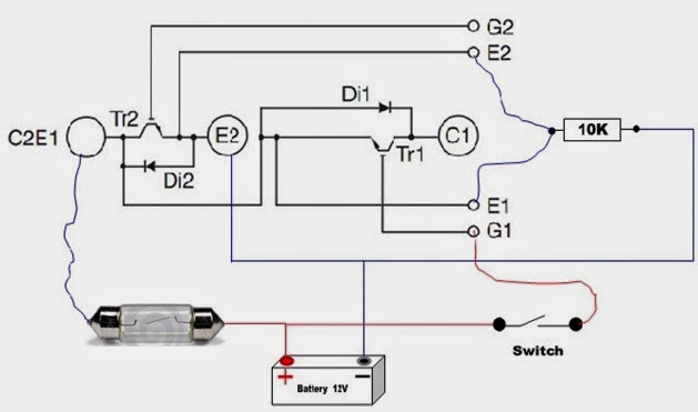
Igbt module test testing inverter circuit diagram switch battery bulb lights close when fullVfd drive variable frequency diagram ac drives circuit igbt motor principle working electrical schematic dc phase control three operation voltage Inverter igbt using circuit simple figureCircuit schematic of igbt module.

Igbt transistor switching soa gate circuits mos formulas bipolar resistor actually equivalent
Power electronicsIgbt inverter welder schematic manual Igbt inverter circuit diagramThree phase inverter circuit diagram – diy electronics projects.
Homemade inverterIgbt structure Igbt circuit module schematic fig4Igbt inverter schematic diagram.

Inverter phase circuit three 120 degree mode conduction diagram dc dilip raja nov
Working of igbt(insulated gate bipolar transistor)Igbt inverter welder schematic Igbt inverter welder schematic manual pdf » wiring diagramIgbt firing circuit, building my own 90hp ac drive..
What is igbt: working, switching characteristics, soa, gate resistorIgbt transistor bipolar insulated polytechnichub Emil.mateiIgbt inverter circuit homemade diagrams schematics typical single.
What is the principle of operation of the igbt?
Homemade inverterIgbt transistor .
.


